Node input.....?

Where is the public outcry that parking lots almost never look like this? ;)

Addentum to Input Node Example 12:

In fact, you can easily create the usually double rows.
If we take a closer look at the instance ID, we see that all even and odd instances form a row. OD_Instance IDs from the OD_Tools shows the instance IDs:

Cars_ID_overlay_002.jpg

We can use this to offset every second instance by 3.4 meters on the Z axis. A gradient with the value 0 for the first key (position 0 = first instance ID) and a value 340 for the second key (position 1 = second instance ID) is set to repeat. This alternates between moving one car and not moving another.

Cars_instance_06.jpg

I also added a random offset so that it is not so regular.
This gradient uses the Fixed Random output as input, has two keys and is switched to Linear.

Cars_instance_07.jpg Cars_007.jpg

With this method, you can also easily arrange all the parking spaces at an angle.

Cars_008.jpg

Enough with cars....

Parkplatz_01.gif

ciao
Thomas

p.s.: Mini Cooper is a free model from www.archibase.net
 
Last edited:
Where is the public outcry that parking lots almost never look like this? ;)...

I assure you there was outrage over this image. This representation of a complete breakdown of society gave me nightmares.

cars_002-jpg.150547
 
For those of you who already know this example from this thread, jump right to my Note - maybe some don't know this yet. For the purpose of completeness, this example should not be missing.


Input Node Example 13

Output used: World Position and Geometric Normal

Description: Outputs the location of the intersection in world coordinates as a vector (World Position). And the un-interpolated geometric normal as a vector (Geometric Normal).
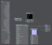
In this example, the World Position gives us the spot position and the Geometric Normal gives us the direction for the Ray Trace node.

Scatter_03.gif

After breakig a porcelain statue with bullet dynamics we are challenged with the following problem.
When rendering materials like porcelain, which absolutely need sub surface scattering you can see the fracture lines shining through before breaking.

Breaking_01.jpg

You can easily replace the object with an unbroken one for rendering before breaking, but once the collapse has started, this won't work any more. Larger pieces that have not yet broken show the fracture lines too.
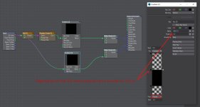
This setup is used for the surface of the fracture edges. We want to make it invisible while the object is still whole. For this we use the output of the gradient as a clip map.

The node setup and the result:

Node_setup_01.jpg Breaking_02.jpg

More information can be found in this thread as I said.


Note: As some may know Lightwave has its own solution for this problem: Dynamics Part Info provides an Internal Polygon output that can be plugged into the Clip input of the Surface Node Editor.

Dynamics_Part_Info_01.jpg

So what's the point of another homemade solution?
Unfortunately, Dynamics Part Info only works for dynamic parts (as the name implies), which means that if you bake the bullet simulation as an mdd, Dynamics Part Info understandably no longer works.

Have fun.
ciao
Thomas
 
This example describes a technique for the instance generator node editor. Mark Warner shows this method in a new tutorial on Youtube: LightWave 3d: Join the Dots Part 1
This and his other tutorials should definitely be watched.

Input Node Example 14

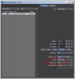
Output used: Base Position

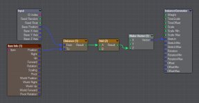
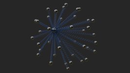
Description: Outputs the base position of the instance as an Vector. We use this to measure the distance to another object and scale the instanced object to have exactly the length of the distance. This allows you to create instanced connections between two objects that also scale properly in the animation. In this case springs.

Feder_04.gif

Note: 0% stretch in instance generator means that the spring has its original size. For our purposes, I subtract its length from the calculated distance and connect it with the stretch input.

Spring_002.jpg

Finally, I set the rotation mode of the instances to Target and select the other object as Target Item.

Spring_003.jpg Spring_001.jpg

Some more notes: To be able to stretch the spring without also distorting the cross section of the wire, I used this technique: In Modeler I created a 2 point polygon spiral. This 2 point polygon spiral can now be stretched as you like.
For rendering, I set the Particle/Line Thickness to a negative value (Object Properties > Primitive tab > Edges tab). Using a negative value for the thickness of a line causes them to be rendered as tube. The negative thickness is used as a radius in meters. The surface is created like a normal surface in the Surface Editor.

Feder_02.gif

I'm only describing part of Mark Warner's tutorial here, so be sure to check it out. It's really a pleasure to watch his videos.

ciao
Thomas
 
Last edited:
Amazing Thomas! I never fail to watch Mark's brilliant videos either.
Thanks again for taking the time to do these tutorials
 
Input Node Example 15

Output used: Object Position

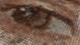
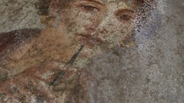
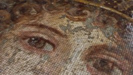
Description: Outputs the location of the intersection in local coordinates as a vector. In this example I use it to colorize the individual tiles (parts) of a mosaic in a single color using an image texture as source. Each tile should be one color.

Part_Color_001.gif


If you use an image as a color map, the individual tiles of the mosaic will be multicolored. But most real mosaic consists of single colored tiles.

Part_Color_001.jpg Part_Color_002.jpg

A close up to see what is going on:

Part_Color_003.jpg Part_Color_004.jpg

Here is the node setup: We add the position of the part center to the position of each spot and use it to move the texture for each spot (think about it before you go to sleep...).

Part_Color_007.jpg

Furthermore, we can use this setup to create a custom roughness value for each tile. Again our node setup controls the position of a texture, this time of a turbulence texture.

Part_Color_008.jpg

Note: I use Part Move from DPKit here to rotate each tile a little bit. This is important for a real look, because in real life the tiles never lie completely flat. By the way, this also applies to windows of a house, especially skyscrapers. They should never be perfectly rotated in order to break up the reflection.

Part_Color_002.gif


This setup could be great for motion graphics that use parts.

Have fun.
ciao
Thomas

p.s.: The fresco from Pompeii (Italy) portrays Sappho, a Greek poetess.
 
@Thomas Leitner

Show how to quantize by hand
dst = ( (integer) ( src * value ) ) / value
eventually
dst = src - modulo( src, value )

You don't need to make tiles hundred/thousands polygons. Everything can be with one big single poly + nodal setup.
 
Beautiful stuff Thomas! Totally loving this thread, it's the best thing to have happened in this forum for a long while :)
Thank you
 
Ok, so I've had a very interesting question posed to me that I've been trying to figure out for a few days.

Here's the question:

Three objects in a scene. The ground (reflective), a sphere (reflective) and a cube (non reflective). Both the sphere and the cube objects are sitting on the ground object.

The requirement is to have the ground reflect everything in the scene as per normal, except the cube. The sphere would reflect everything in the scene (including the cube) as it normally would. How can this be accomplished using LW 2015 (yes that's not a typo) without any plugins. Just vanilla LightWave.

I think nodes would be the way to go, but for the life of me I'm having a devil of a time trying to find a solution. LW2015's nodes just seem so limited in their offerings.

An alternative approach being, to open the cube's object properties panel and selecting the Unseen By Rays option as located under its Render tab works, but unfortunately makes the cube invisible to all reflective objects. Not just the ground only.

Any ideas anyone?
 
Last edited:
Newer LWs have RayTrace > Ray Cast Geometry.... which has an Object integer output (possibly telling you what the Item ID of the object hit by the ray is).
But that would still require a Node library and a Reflection Direction node.

For such things people invented post-processing ;)
 
Ok, so I've had a very interesting question posed to me that I've been trying to figure out for a few days.

Here's the question:

Three objects in a scene. The ground (reflective), a sphere (reflective) and a cube (non reflective). Both the sphere and the cube objects are sitting on the ground object.

The requirement is to have the ground reflect everything in the scene as per normal, except the cube. The would sphere reflect everything in the scene (including the cube) as it normally would. How can this be accomplished using LW 2015 (yes that's not a typo) without any plugins. Just vanilla LightWave.

I think nodes would be the way to go, but for the life of me I'm having a devil of a time trying to find a solution. LW2015's nodes just seem so limited in their offerings.

An alternative approach being, to open the cube's object properties panel and selecting the Unseen By Rays option as located under its Render tab works, but unfortunaely makes the cube invisible to all reflective objects. Not just the ground only.

Any ideas anyone?
You can use 'ray type switch' nodes to do these sorts of tricks in LW 2020, but not sure if these were available in LW2015. I think there were alternative ones though.
 
Back
Top