- Home
- Forums
- Historical Records
- Lightwave
- LightWave 3D Technique Discussions
- Node Library and Workshop
You are using an out of date browser. It may not display this or other websites correctly.
You should upgrade or use an alternative browser.
You should upgrade or use an alternative browser.
Node input.....?
- Thread starter Markc
- Start date
Thomas Leitner
Member
Addentum to Input Node Example 5:
You can, of course, animate the positions of the keys of the gradient and curve.
For the curve node I used Channel Follower to follow a scalar node (scalar(1)) that also controls the position of the last key of the gradient.
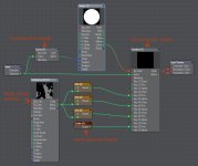
Ok, for all of you who can't follow this now there is the scene file below.
Some notes: Since I wanted to have some noise that would not disturb the outer shape of the flame I added a texture only to the key positions of the gradient (not to the curve node).
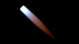
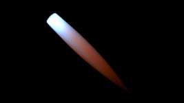
Because I wanted stripes instead of specks I use a 2D texture in the Z axis (the direction in which a light looks by default).
With a 3D texture (specks):
With a 2D texture on the z axis (streaks):
Some more notes: You can really do crazy things with this setup. This is what it looks like when you take a square image instead of a circle image and rotate it around the Z axis depending on the Distance.

And here compined with the Curve node.

Have fun
Thomas
You can, of course, animate the positions of the keys of the gradient and curve.

For the curve node I used Channel Follower to follow a scalar node (scalar(1)) that also controls the position of the last key of the gradient.

Ok, for all of you who can't follow this now there is the scene file below.
Some notes: Since I wanted to have some noise that would not disturb the outer shape of the flame I added a texture only to the key positions of the gradient (not to the curve node).
Because I wanted stripes instead of specks I use a 2D texture in the Z axis (the direction in which a light looks by default).
With a 3D texture (specks):

With a 2D texture on the z axis (streaks):

Some more notes: You can really do crazy things with this setup. This is what it looks like when you take a square image instead of a circle image and rotate it around the Z axis depending on the Distance.

And here compined with the Curve node.

Have fun
Thomas
Attachments
Thomas Leitner
Member
A fast one.
Input Node Example 6
Output used: Item ID
Description: Outputs the Item ID.
The Item ID has encoded the item type too (That's why it's so long and confusing). For what I have in mind, I do not need this additional information. Therefore I simply subtract the unnecessary value and get a numbering of the objects starting with 1.
Note: You can get the item ID for all items with the item ID node.
For example, you can use this numbering to control a gradient.
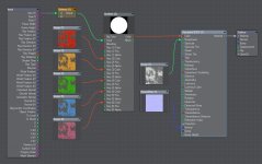
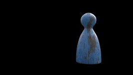
If you clone the object now, you automatically get different surfaces.
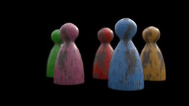
Here are only 5 objects, but of course it works for hundreds.
This could be solved with instances too, but sometimes clones are necessary...
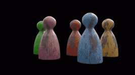
ciao
Thomas
Input Node Example 6
Output used: Item ID
Description: Outputs the Item ID.
The Item ID has encoded the item type too (That's why it's so long and confusing). For what I have in mind, I do not need this additional information. Therefore I simply subtract the unnecessary value and get a numbering of the objects starting with 1.
Note: You can get the item ID for all items with the item ID node.
For example, you can use this numbering to control a gradient.


If you clone the object now, you automatically get different surfaces.

Here are only 5 objects, but of course it works for hundreds.
This could be solved with instances too, but sometimes clones are necessary...

ciao
Thomas
@Thomas Leitner
Make:
Example #1 animation-transition from Geometric Normal to Smoothed/Perturbed Normal.
Example #2 control weight map which tells whether Normal should be taken from Geometric Normal or from Smoothed/Perturbed Normals.
(so you have object having both hard edges and smooth edges at the same time)
Make:
Example #1 animation-transition from Geometric Normal to Smoothed/Perturbed Normal.
Example #2 control weight map which tells whether Normal should be taken from Geometric Normal or from Smoothed/Perturbed Normals.
(so you have object having both hard edges and smooth edges at the same time)
Thomas Leitner
Member
Example #1 animation-transition from Geometric Normal to Smoothed/Perturbed Normal.
Example #2 control weight map which tells whether Normal should be taken from Geometric Normal or from Smoothed/Perturbed Normals.
(so you have object having both hard edges and smooth edges at the same time)
Input Node Example 7
Output used: Geometric Normal, Smooth Normal
Description: Outputs the un-interpolated geometric normal (Geometric Normal) and interpolated normal (Smooth Normal) as a Vector.
In this example, I blend between the Smooth Normal and the Geometric Normal. An animated black and white image controls the gradient. This simple example could be solved faster in compositing but this method works in 3D space with animated objects too.


Note: In order to use the Smoothed Normal output you need to check Smoothing in the Surface Editor.
As Sensei said, you can also control the blending with a weight map.
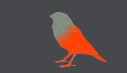

ciao
Thomas
Last edited:
Thomas Leitner
Member
Input Node Example 8
Output used: Ray Type
Description: Outputs the ray type (Camera ray, Reflection ray, Refraction ray, Dissolve ray, Shadow ray and Occlusion ray).
You can use it to switch between materials depending on the ray type. This means that a surface can change its appearance when you look at it through glass, for example.
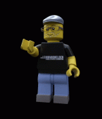
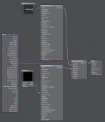
Note: The Ray Type Switch node seems to work without Ray Type input (The manual is not clear on this). However, it is still useful. You can also use the Ray Type output to control a gradient and switch almost everything depending on the Ray Type. Of course, you can also use it for less noticeable but useful things like enhancing the brightness of a reflection and so on.
This are original renders with a bit of glow added in post:
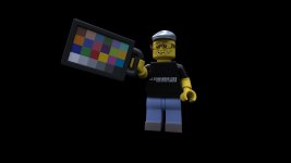
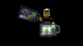

Have fun
ciao
Thomas
Output used: Ray Type
Description: Outputs the ray type (Camera ray, Reflection ray, Refraction ray, Dissolve ray, Shadow ray and Occlusion ray).
You can use it to switch between materials depending on the ray type. This means that a surface can change its appearance when you look at it through glass, for example.

Note: The Ray Type Switch node seems to work without Ray Type input (The manual is not clear on this). However, it is still useful. You can also use the Ray Type output to control a gradient and switch almost everything depending on the Ray Type. Of course, you can also use it for less noticeable but useful things like enhancing the brightness of a reflection and so on.

This are original renders with a bit of glow added in post:


Have fun
ciao
Thomas
Last edited:
Thomas Leitner
Member
This is what I going to say, missing him. Hope he will come back.these remind me so much of Gerardo Estrada's threads
Thomas Leitner
Member
Many will already know this example, but I think it should not be missing in this collection. It uses the Input node of Nodal Motion, a modifier in the Motion Options.
Input Node Example 9
Output used: Item Position
Description: Outputs the position of the item.
The Input Node gives us the pre animated position of the IK controller so we can modify it using the Ray Cast geometry node.
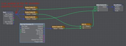
To walk on uneven terrain.

or, um...

Here you can find more details about the special usage.
And here, for those who don't know it yet, the making of of the swim tire gif.
Note: In the original example with the spider, I don't use the Input Node at all yet. The example is older and I don't remember why I didn't use it then. But it shows very well what you can avoid with the help of the input node.
ciao
Thomas
Input Node Example 9
Output used: Item Position
Description: Outputs the position of the item.
The Input Node gives us the pre animated position of the IK controller so we can modify it using the Ray Cast geometry node.

To walk on uneven terrain.

or, um...

Here you can find more details about the special usage.
And here, for those who don't know it yet, the making of of the swim tire gif.
Note: In the original example with the spider, I don't use the Input Node at all yet. The example is older and I don't remember why I didn't use it then. But it shows very well what you can avoid with the help of the input node.
ciao
Thomas
Thomas Leitner
Member
This is an example of the Displacement Node Editor.
Input Node Example 10
Output used: Current Position
Description: Outputs the current deformed vertex position in object coordinates (Vector).
You need it when you use the Deform nodes (among others).
Here is a simple setup for the Bend node. We hook Current Position from the Input node into Point Position on Bend deformer. Two null objects control the bend (base and handle).
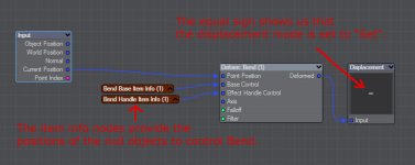
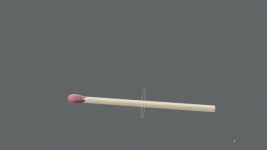
You can plug the individual Deform nodes one after the other. The output goes into the Point Positions input of the next one.
Here is a simple node tree with scale, twist and bend deformer. Additionally a Turbulence texture is added to make it more organic. That's all it takes to create the deformation.

Note: The Displacement destination node Mode must be set to "Set". Each deform node processes the output (= displacement) of the previous one, you should keep this in mind during setup.
Happy deforming.
ciao
Thomas
Input Node Example 10
Output used: Current Position
Description: Outputs the current deformed vertex position in object coordinates (Vector).
You need it when you use the Deform nodes (among others).
Here is a simple setup for the Bend node. We hook Current Position from the Input node into Point Position on Bend deformer. Two null objects control the bend (base and handle).


You can plug the individual Deform nodes one after the other. The output goes into the Point Positions input of the next one.
Here is a simple node tree with scale, twist and bend deformer. Additionally a Turbulence texture is added to make it more organic. That's all it takes to create the deformation.


Note: The Displacement destination node Mode must be set to "Set". Each deform node processes the output (= displacement) of the previous one, you should keep this in mind during setup.
Happy deforming.
ciao
Thomas
Last edited:
Thomas Leitner
Member
This method is used by Oliver Hotz in some of his Buffer/Passes plugins from his OD Tools.
Input Node Example 11
Output used: Ray Weight
Description: Outputs the accumulated weight of the ray represented as a color.
Here we use it to create an antialiased mask for a surface. The nativ Surface ID buffer is not antialiased (for good reason), but sometimes you need an antialiased surface mask.
To generate a mask, you must first create a custom buffer (Render Properties > Buffer tab).
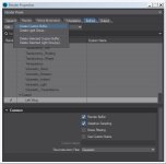
In the Surface Editor of the desired surface, plug the Ray Weight output into the new created buffer input.

Done.

Note: You can of course plug several surfaces in the same buffer to combine them into one mask.
ciao
Thomas
Input Node Example 11
Output used: Ray Weight
Description: Outputs the accumulated weight of the ray represented as a color.
Here we use it to create an antialiased mask for a surface. The nativ Surface ID buffer is not antialiased (for good reason), but sometimes you need an antialiased surface mask.
To generate a mask, you must first create a custom buffer (Render Properties > Buffer tab).

In the Surface Editor of the desired surface, plug the Ray Weight output into the new created buffer input.

Done.

Note: You can of course plug several surfaces in the same buffer to combine them into one mask.
ciao
Thomas
Last edited:
Whoa.This method is used by Oliver Hotz in some of his Buffer/Passes plugins from his OD Tools.
Input Node Example 11
Output used: Ray Weight
Description: Outputs the accumulated weight of the ray represented as a color.
Here we use it to create an antialiased mask for a surface. The nativ Surface ID buffer is not antialiased (for good reason), but sometimes you need an antialiased surface mask.
And this is using native LW? No plugins?
Thomas Leitner
Member
Whoa.
And this is using native LW? No plugins?
Yes, no plugins. Oliver's tools help to make this setup with one click but use native Lightwave.
chunderburger
Well-known member
yes, fantastic info, thanks Thomas. Hopefully one day, Gerardo returns. I am sure he would love this one.This thread gets better and better
Awesome examples, these remind me so much of Gerardo Estrada's threads, beautiful eye-candy and mega useful info
Thomas Leitner
Member
This example is for the Node Editor of the Instance Generator.
Input Node Example 12
Output used: Fixed Random or ID Index
Description: Outputs a random scalar between 0 and 1 (Fixed Random) or the ID of each instance (ID Index).
In this example I use it to control the rotation of the instances.

Normally, you can easily create a random rotation of instances. To do this, set a minimum and maximum rotation for the desired axis in the Rotation tab.

However, if you want a random rotation in fixed steps, this does not work here.

A simple node setup does the job. You control a gradient with the Fixed Random output. The gradient has two keys with a value of 0 and 314.159 both set to Step. The unit for the rotation is radian. 314.159 means 180° (actually it is 3.14159 but internally Lightwave reads 100% as 1 ..... ).
).
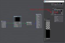
I prefer to use an angle node instead because I don't always want to convert to radians.


Of course, you can extend the rotation to a small range around 0° and 180° so that not all cars are completely straight.

Because I control the color of the cars also with the fixed random output all cars of one color are in the same direction.
This is not so noticeable here but can be very annoying in other situations.
To correct this, I'm adapting the setup a bit. The ID Index output now provides the seed input for a Random Scalar node, which controls the gradient.
The Add node gives the possibility to change the seed easily.
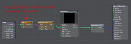

Finally, I added a little randomness to the offset (position).

Note: if you want to use the Node Editor to control rotation you have to set the rotation to Uniform in the Rotation tab of the Instance Generator.
ciao
Thomas
Input Node Example 12
Output used: Fixed Random or ID Index
Description: Outputs a random scalar between 0 and 1 (Fixed Random) or the ID of each instance (ID Index).
In this example I use it to control the rotation of the instances.

Normally, you can easily create a random rotation of instances. To do this, set a minimum and maximum rotation for the desired axis in the Rotation tab.

However, if you want a random rotation in fixed steps, this does not work here.

A simple node setup does the job. You control a gradient with the Fixed Random output. The gradient has two keys with a value of 0 and 314.159 both set to Step. The unit for the rotation is radian. 314.159 means 180° (actually it is 3.14159 but internally Lightwave reads 100% as 1 .....

I prefer to use an angle node instead because I don't always want to convert to radians.


Of course, you can extend the rotation to a small range around 0° and 180° so that not all cars are completely straight.

Because I control the color of the cars also with the fixed random output all cars of one color are in the same direction.
This is not so noticeable here but can be very annoying in other situations.
To correct this, I'm adapting the setup a bit. The ID Index output now provides the seed input for a Random Scalar node, which controls the gradient.
The Add node gives the possibility to change the seed easily.


Finally, I added a little randomness to the offset (position).

Note: if you want to use the Node Editor to control rotation you have to set the rotation to Uniform in the Rotation tab of the Instance Generator.
ciao
Thomas
Last edited:

