- Home
- Forums
- Historical Records
- Lightwave
- LightWave 3D Technique Discussions
- Node Library and Workshop
You are using an out of date browser. It may not display this or other websites correctly.
You should upgrade or use an alternative browser.
You should upgrade or use an alternative browser.
Node input.....?
- Thread starter Markc
- Start date
It is essential for anything more complex..Has anyone ever used the input node that is in every surface.
I usually just minimise it.
Not sure what it's purpose is.
See my YouTube videos.
I am using it A LOT.
It used to be called Spot Info in earlier times (and earlier videos). But purpose is the same.
Example: World Position from Input/Spot Info plugged to Distance, along with Item Info > World Position, to get distance between them. Then plugged to e.g. Gradient to change distance to scalar or color.
Yes. I have, and do.Has anyone ever used the input node that is in every surface.
Thomas Leitner
Member
As Sensei said, the Input Node is the replacement for the Spot Info node.
As a addition for all those who are not familiar with the spot info:
It provides access to information regarding the current hit point being evaluated. For surfaces, this basically means for each pixel of the rendered surface.
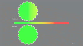
For comparison: With the help of a gradient we color the surface of two objects.
For one, we use the world position output of the item info to control the gradient.
Item info returns the position of the objects pivot point. The whole surface has the same color, depending on the position of the object.
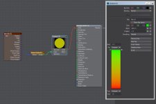
For the other we use the world position output of the input node to control the gradient..
This gives us an indivitual color for each spot of the surface. Since we are using world position output, the color here also changes depending on the position of the object.

The two objects:
Maybe it would be useful to collect a few use cases for the input node in this thread.
ciao
Thomas
As a addition for all those who are not familiar with the spot info:
It provides access to information regarding the current hit point being evaluated. For surfaces, this basically means for each pixel of the rendered surface.
For comparison: With the help of a gradient we color the surface of two objects.
For one, we use the world position output of the item info to control the gradient.
Item info returns the position of the objects pivot point. The whole surface has the same color, depending on the position of the object.

For the other we use the world position output of the input node to control the gradient..
This gives us an indivitual color for each spot of the surface. Since we are using world position output, the color here also changes depending on the position of the object.

The two objects:

Maybe it would be useful to collect a few use cases for the input node in this thread.
ciao
Thomas
Thomas Leitner
Member
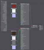
Input Node Example 1
Output used: Surface Side
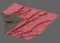
Description: Determines if the intersection hit the front (output = 0) or back (output = 1) of the surface.
This allows you to separate the front and back sides of a polygon (surface).
A very simple setup, but often usable.
Usually a polygon has only one visible side, from the other it is invisible. If you switch it to double-sided, it will have the same material on both sides. With a simple node setup you can assign two different materials to the front and the back side of the polygons.
Note: the surface must be set to double-sided.
ciao
Thomas
Output used: Surface Side
Description: Determines if the intersection hit the front (output = 0) or back (output = 1) of the surface.
This allows you to separate the front and back sides of a polygon (surface).
A very simple setup, but often usable.
Usually a polygon has only one visible side, from the other it is invisible. If you switch it to double-sided, it will have the same material on both sides. With a simple node setup you can assign two different materials to the front and the back side of the polygons.
Note: the surface must be set to double-sided.


ciao
Thomas
Evaluated spot might be seen from reflection and/or refraction (and not visible directly). sub-pixel in anti-aliasing procedure. etc.For surfaces, this basically means for each pixel of the rendered surface.
Make an example with a couple spheres which have the same surface. Assign color depending on the number of reflection bounces which happened. Sphere seen from other sphere will have different color. It might be used to assign different quality image map in the real example e.g. more blurred.
Thomas Leitner
Member
Make an example with a couple spheres which have the same surface. Assign color depending on the number of reflection bounces which happened. Sphere seen from other sphere will have different color. It might be used to assign different quality image map in the real example e.g. more blurred.
I did it with a cube (with spheres, the reflections become very small very quickly).
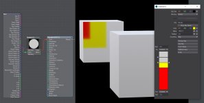
Input Node Example 2
Output used: Bounce
Description: The number of bounces the ray has taken to reach this intersection (starts at 1).
Two simple light gray metallic cubes reflect each other. Bounce output from the input node controls a gradient. With each bounce the cubes change their color.
ciao
Thomas
Thomas Leitner
Member
Ok, this is not an example for the Surface editor but for the Instance Generator. Like the other node editors, this one also has an input node.
Input Node Example 3
Output used: Base Position
Description: Outputs the base position of the instance.
In this scene the output is used to determine if the individual instance is inside another object.
The Ray Cast Geometry node is used for this purpose. The gradient outputs black or white.
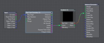
The idea behind this is that all instances that are not inside the object are scaled to 0 (become invisible). What remains visible are the instances that form the shape of the object. Here they are lego blocks...
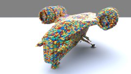
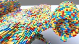
Note: To get a closed hull of the Razor Crest (I used a free model from CGTrader ) for the Ray Cast geometry node I used a handy tool from OD Tools: OD Create VDB as Proxy (you find the documentation and video here). It generates a proxy geometry in seconds.
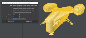
To be honest, Razor Crest is not the most suitable object for this purpose. It has too thin parts.
ciao
Thomas
Input Node Example 3
Output used: Base Position
Description: Outputs the base position of the instance.
In this scene the output is used to determine if the individual instance is inside another object.
The Ray Cast Geometry node is used for this purpose. The gradient outputs black or white.

The idea behind this is that all instances that are not inside the object are scaled to 0 (become invisible). What remains visible are the instances that form the shape of the object. Here they are lego blocks...


Note: To get a closed hull of the Razor Crest (I used a free model from CGTrader ) for the Ray Cast geometry node I used a handy tool from OD Tools: OD Create VDB as Proxy (you find the documentation and video here). It generates a proxy geometry in seconds.

To be honest, Razor Crest is not the most suitable object for this purpose. It has too thin parts.
ciao
Thomas
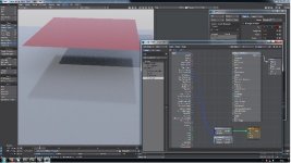
Spot Info (now Input) have outputs World Position and Ray Direction, which can be, and usually are, inputs to ray tracing nodes i.e Ray Trace and Ray Cast (they have default 0,0,0 origin and direction, which are rather useless).
Normal surface:
After detection if there is geometry behind:
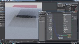
RayCast can be used to learn whether there is geometry in specified direction.
Here I am using Input > Ray Direction (i.e. the one which ray would take if would not hit our geometry).
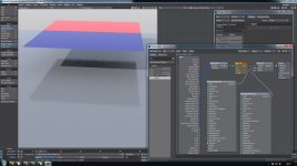
It could be used to make objects which are only visible in specific range of distances from camera and/or other other object (after reflection/refraction), or below some threshold, or after some threshold.
Normal surface:

After detection if there is geometry behind:

RayCast can be used to learn whether there is geometry in specified direction.
Here I am using Input > Ray Direction (i.e. the one which ray would take if would not hit our geometry).

It could be used to make objects which are only visible in specific range of distances from camera and/or other other object (after reflection/refraction), or below some threshold, or after some threshold.
Last edited:
Try Right clicking the image and selecting "Open image in new tab" (if you're using Chrome).Sorry to be a pain, but is it possible to make those images clickable to enlarge? i'm struggling to see exactly what's going on in them.
EDIT:
Nope, sorry. I don't think that'll do any good, the images seem to be scaled down to a low resolution by the poster.
Oh, sorry, too large resize down it seems..i'm struggling to see exactly what's going on in them.
But I described: World Position and Ray Direction from Input/Spot Info, are plugged to Ray Cast/Ray Trace nodes, then to Logic node and finally used as Clip and as Material Switch.
Logic in mode Greather Than 1000 or so was used.
lardbros
Not so newbie member
Yeah, I tried that too... LolTry Right clicking the image and selecting "Open image in new tab" (if you're using Chrome).
EDIT:
Nope, sorry. I don't think that'll do any good, the images seem to be scaled down to a low resolution by the poster.
You can just about make it out, but it's just slightly blurry that's all
Thomas Leitner
Member
This is a really quick example for the light node editor.
Input Node Example 5
Output used: Distance
Description: Outputs the distance from the light source.
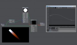
We can use this to color the light beam.
I used a spot light with Affect Volumetrics turn on (enabled Volumetric Scattering in the Render Properties too)
In the light Node Editor I used a gradient to color the light depending on the length of the beam.
Note: you can use colors with values more than 255. Very useful especially for lights.

With the help of a Curve node you can shape the light beam. The Curve node controls the size of an image (a white circle on a black background) and thus the diameter of the light beam. The image is multiplied by the gradient.
Note: In the image node set U and V Tiling to Edge.
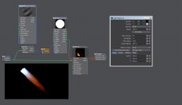
I added a Ripples texture.
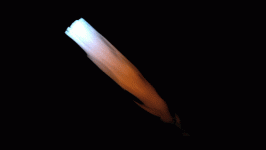
Attention: You can easily play for hours with this setup.
ciao
Thomas
Input Node Example 5
Output used: Distance
Description: Outputs the distance from the light source.
We can use this to color the light beam.
I used a spot light with Affect Volumetrics turn on (enabled Volumetric Scattering in the Render Properties too)
In the light Node Editor I used a gradient to color the light depending on the length of the beam.
Note: you can use colors with values more than 255. Very useful especially for lights.

With the help of a Curve node you can shape the light beam. The Curve node controls the size of an image (a white circle on a black background) and thus the diameter of the light beam. The image is multiplied by the gradient.
Note: In the image node set U and V Tiling to Edge.

I added a Ripples texture.


Attention: You can easily play for hours with this setup.
ciao
Thomas
lardbros
Not so newbie member
Was going to say the exact same thing.Just wanted to say that I don't know about anyone else, but I'm really enjoying this thread & please keep it up.
Such a brilliant thread, live what everyone is posting! Thanks.
