Industrial Tunnel Environment (Pipes and Wires)

SA9R

New member


Modeled and rendered in Lightwave.
Rendered in Maxwell.

Made lots of use of LW's pipe tools: Rail Extrude tool with splines, Spline Guide tool and Magic Bevel.
Also used LW's off-axis tools, because most of the walls are off-axis: Align and Transform Tool.

It would be great if LW developed more off-axis tools that allow using a selected polygon's normal to define the work plane for the tool.
 
Last edited:
Images:

1. Concept Art
2. LW Modeler Wires
3. LWR Final Render with White/Black Points changed in Image Controls, to push the light back further.
4. Maxwell Render
 
Last edited:
Updated the image.

The model now includes the perpendicular tubes in the circular conduit. A piece of paper there too. And the little grommets on the small curvy wire have been added for... completeness.
 
Is it your intent to create an interpretation of the original art or a more precise rendition? I ask because the scale of most elements in your version seems off: cables are too thick, the curves of a number of the pipe work is different and most elements decorating the tunnel are oversized compared to the original drawing. The ladder sports don't match the original either.

The overall result is that the original art's sense of scale and your version do not match and are actually quite different.

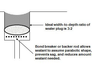
PS The black stuff between the concrete slabs is probably a sealant to accommodate their expansion and contraction. When it was applied some of the stuff ran down in black streams here and there in the drawing. The inner shape of the joints would look a bit like this (you can sort of make this out in the original drawing when you know what to look for - it might be receded along the edges here and there as well):

bill-palmer_10891.jpg


Anyway, continue the good work.
 
True, it is not a perfect match. To some degree it is a generalization. A closer match would take much more time than suits the current use. Blocking in the different shapes first to match the basic proportions was done first and he "Layout View" in viewports was very useful. Still, the perspective was difficult to match with the camera and there are things in the illustration that do not make perfect sense in 3D. For example, the sections of concrete couldn't be the same size and still have their connecting lines in the same place as in the illustration. In 3D, the ones closest to the camera are actually about 1/3rd the size of the others just to better match the concept art. The illustration is masterful as conveying a feeling with a good amount of technical draftsmanship.

About the sealant. Very interesting. I wonder. Hadn't thought of that idea. There could be more mundane or fantastic causes. In mundane land, it could be the result of humidity, dust and mechanical oil over very long periods of time. In fantastic land, the concrete slabs might be what separates the inside from thick, dirty black goo, a city submerged and kept separate from the thick blackness around it.

I wondered how much people might notice the differences or not. Thank you.
 
Interestingly, I used OSHA's Fixed Ladder requirements as the basis for the ladder rungs:

"Rung Spacing: 10" minimum and 14" maximum spacing from centerline to centerline of rungs. There are exceptions for ladders in elevator shafts or on telecommunications towers. Note: ANSI A14.3-2008 calls for exactly 12" spacing of rungs (the first rung can be up to 14" from the floor surface.)

Rung Width: The minimum clear width of rungs on fixed ladders shall be 16". Note: The International Mechanical Code 2018 (306.5.4) calls for a minimum of 18" between rails. This width increases to 24" clear at the top of the ladder where the side rails extend 42" above the deck."

I didn't even know they had that until I looked it up. And... it still didn't look right, so I changed it.
 
Yes, drawings can be fooling the eye in so many ways, yet remain convincing :)

Things like the rung specs I also investigate before I model something. And at times I get lost in the research too much...
 
Updated the image.

Changed the two tubes on the left. I couldn't get the curves right so they looked like Chinese fried noodle snacks without the benefit of being able to eat them. So, I just made them straight.

Also added subdivision to all the tubes.
 
hat is as close as it will get for this scene. Concept art can be half technical drafting and half M.C. Escher. Makes for an interesting puzzle for the 3D artist. T
 
Back
Top