You are using an out of date browser. It may not display this or other websites correctly.
You should upgrade or use an alternative browser.
You should upgrade or use an alternative browser.
Industrial Liquid Metal Drill: Basic Lightwave & Maxwell GI Renders
- Thread starter SA9R
- Start date
prometheus
REBORN
You are just not using it right, metallic looks with PBR and the newer render engine.. should be by far better in Lightwave 2018 and up compared to standard materials.I tried doing a metal surface on just a plain object in direct lighting and got absurdly bad results. Quite surprising considering that I could get perfectly good results in previous versions. The renderer was a downgrade. Good thing I have Maxwell.
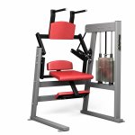
I used to do some gym renderings 2010-2012, old standard materials.. I so wish I had the pbr materials then and the new light´s, but better yet..wish I had blender then, because that´s what I would use for faster renders.
So images below, Lightwave 10-11 I believe, and they would have looked much better with the new pbr Materials and lights.
Our constructor tried to render it out with maxwell at that time, but it took like 12 hours or more to wait for the renders, that´s where I jumped in and said we could do this faster with Lightwave, within a couple of minutes, to 30 minutes or so.
The clean non dirty up rendering ..is there by intention.
You could lurk around youtube for blender pbr, metallics, product shots, and see how that works, principles are similar to Lightwave ..and you can draw from that, either using Lightwave or blender, anisotrophics works straight out of the bat with blender, while you need to dig in to the nodal editor and set up maps for that in Lightwave.
so if you try to use anisotrophy without it in Lightwave, you would get uggly artifacts.


Last edited:
lardbros
Not so newbie member
If you're using the PBR shader in LW 2018, all you need is the Principled shader, and metalness at 90%+. Maybe a bit of roughness. LW's renderer is more than capable, but I'd kind of think your render settings are probably above what you require.
That many bounces of GI, in LW, the difference tends to be barely visible above 5.
Also, the adaptive sampling seems to be quite high... but again, maybe I've got the wrong idea of what your settings are.
Does look nice though so far. How are you doing the fluids, using Phoenix?
That many bounces of GI, in LW, the difference tends to be barely visible above 5.
Also, the adaptive sampling seems to be quite high... but again, maybe I've got the wrong idea of what your settings are.
Does look nice though so far. How are you doing the fluids, using Phoenix?
prometheus
REBORN
Hard to say with this, don´t know how enclosed the cyce/room is, it is needed for bouncing light.
hard to say, how many light´s..which types, you would probably need some area lights to give reflections as well, not just a sunlight, if there´s a sunlight, there´s got to be a window, you just don´t throw in a sunlight as it is, it´s outside of the window
So boost it up with additional lights, or reflector geometry, emissive geometry, or use a studio HDR image.
use glossy shading on, metal shiny chrome has low rougness, metal industrial machine parts often much higher roughness, and often some type of anisotrophy and bump noise for it´s brushed part.
prometheus
REBORN
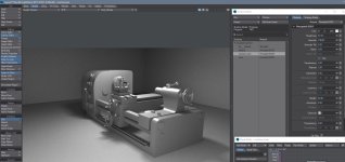
And a sample of what anisotrophy can highlight on the mesh form, with and without.
I did limit the reflection a bit to avoid fireflies a bit here and speeding up of solving that without any noise reduction, so reflections can be improved, but I would need to fix other settings in such case
Make sure you have glossy reflections on, yes it will introduces fireflies, but without it, no proper reflections.
make sure to have a projection map applied in the pbr surface, for anisotrophy to work properly, see my material settings, which could be optimized more, I just dial in right now a quicky, you can try the preset metal materials and add anisotrophy for them as well, roughness around 57 % for a decent effect with the anisotrophy as well.
GI is on, three lights only, and they are all area lights, one at the ceiling, one to the side, on just in front of the camera like a flash light, positioned exactly at the camera position and the same direction as well.
But nothing more really than to show anisothrophy, model isn´t that good, just a sample from sketchup(Serge Shavin) without any proper edge bevels, a perfect receipe for failure in realism, unless using edge shaders.
Especially check the round parts on the machine where the anisotrophy effect works best, you may need to rotate the anisotrophy, depending on what map you have, further enhancements with that would include bump/normal mapping, which I do not have time for now.
Anisotrophy would have helped on your pipe sections to provide a sense of roundess on the pipes, as well as overall on your machine, and a metallic sense if that is the surface they should be of.
Too high metallic value, and it becomes very dark and contrasted, so not too much of that unless very chrome stylish, same with dark or white color for the surface...and same with too low roughness.


prometheus
REBORN
same Model as above ..but with textures, the one I first tested was dae file type, for opening in Lightwave, couldn´t bother with re-assigning textures though.
Tried the gltf model in some other software, just one sunlight though, should use area lights for the real thing though.
there are rougness maps and much much more on the full textured version.
Model can be found here...
Desk Lathe - Download Free 3D model by Sergey Shavin (@ssh-72) [7b7ef0c] (sketchfab.com)
Rendered on something else than Lightwave within a 5 second specified limit with GPU raytrace, the realtime version also looks good, I didn´t try anisotrophy on this one though, may do that later....

If checking this on sketchfab, hold down alt, left mouse drag to change the HDR image source lighting in realtime.
Tried the gltf model in some other software, just one sunlight though, should use area lights for the real thing though.
there are rougness maps and much much more on the full textured version.
Model can be found here...
Desk Lathe - Download Free 3D model by Sergey Shavin (@ssh-72) [7b7ef0c] (sketchfab.com)
Rendered on something else than Lightwave within a 5 second specified limit with GPU raytrace, the realtime version also looks good, I didn´t try anisotrophy on this one though, may do that later....

If checking this on sketchfab, hold down alt, left mouse drag to change the HDR image source lighting in realtime.
Nice models. Modeling gym machines is one way of working out.
I used super high AA sampling because all light and render engine samples are set to 1. It is also almost all indirect lighting which takes many samples to fill in. This arrangement allows for better tuning of the amount of AA samples needed in a render, I think. I did not tune the AA sample setting much though.
I might have gotten a better grasp of the reflections in LWR, similar to what was being recommended here by you guys.

I found three interesting things:
1. Standard shaders have no reflection blur. Glossy reflections is doing nothing.
2. BSDF shaders do have reflection blur though the BSDF shaders do not show their full fresnel style shading unless rec709 color space is used.
3. VPR only renders in linear color space, and the full BSDF fresnel shading is not visible until having the VPR color space set to rec709 and pressing the save image viewport button.
In the image, the top image is the VPR render viewport and it shows linear color space which does not show good reflection shading in BSDF. The very top of the balls fade perfectly into the black background instead of having a reflective sheen. The bottom image is the sane VPR viewport's render saved as an image, using the rec709 color space. Looks good. I wish that could be seen in the VPR viewport during rendering. It would help with fine tuning material settings.
If you look at the ground surface, the reflection looks awful. It is just the reflections from the roughness channel being set to 0. That is what I was talking about before.
I tried the metalic channel in the industrial workshop scene, but it only seemed to produce darkness. Maybe I will try it again and get a better balance between the roughness channel and the metalic channel as well as set it to the recc709 color space as is done in the image above.
I used super high AA sampling because all light and render engine samples are set to 1. It is also almost all indirect lighting which takes many samples to fill in. This arrangement allows for better tuning of the amount of AA samples needed in a render, I think. I did not tune the AA sample setting much though.
I might have gotten a better grasp of the reflections in LWR, similar to what was being recommended here by you guys.

I found three interesting things:
1. Standard shaders have no reflection blur. Glossy reflections is doing nothing.
2. BSDF shaders do have reflection blur though the BSDF shaders do not show their full fresnel style shading unless rec709 color space is used.
3. VPR only renders in linear color space, and the full BSDF fresnel shading is not visible until having the VPR color space set to rec709 and pressing the save image viewport button.
In the image, the top image is the VPR render viewport and it shows linear color space which does not show good reflection shading in BSDF. The very top of the balls fade perfectly into the black background instead of having a reflective sheen. The bottom image is the sane VPR viewport's render saved as an image, using the rec709 color space. Looks good. I wish that could be seen in the VPR viewport during rendering. It would help with fine tuning material settings.
If you look at the ground surface, the reflection looks awful. It is just the reflections from the roughness channel being set to 0. That is what I was talking about before.
I tried the metalic channel in the industrial workshop scene, but it only seemed to produce darkness. Maybe I will try it again and get a better balance between the roughness channel and the metalic channel as well as set it to the recc709 color space as is done in the image above.
prometheus
REBORN
Yeah, I didn´t do anything of it though, models mostly done in solidworks by an engineer, then I took over with surfacing, lighting, texturing, rendering, adding modeled welding seems, modeling the cushions I did as well.
And while we had some running machines, in the same office as we worked, I only took a few steps on it, it was to boring to do excercise inside, I rather walk outside in the nature.
VPR can render in whatever you set the color space to be in, if you choose color space presets as disabled (linear settings) or srgb orr ec 709.
You are pumping your GI up Way beyond what is necessary...
The problem of judging your scene properly, we do not know how many lights you have, what types they are, and how your environment is set up, if you have no geometry cyce background or room, there´s not much to bounce, and you would have to fake that with a white background color that serves as the GI emission.
if you don´t want to use PBR, use the older conductor material for metallics, roughness increased is reflection blur.
If you set anisotrophy on, it will yield artifacts same as PBR, you have to enter nodal editing and add a projection map.
For my renders of that industrial machines (not the gym machine that was Lightwave 11)
It wasn´t vray, it was blender cycles, and I chose to set 5 sec as a limit, could set it to 3seconds and get semidecent as well, or switch to evee and have millisecond rendering that looks fairly good still, so it´s nice to be able to choose how long I want it to render, and not just guess on it.
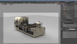
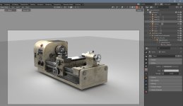
Samples below of no light at all except from the background in blender, principles are the same in Lightwave, but slower to render over here
Then one area light
Next second area light
and a third area light last image, activated the room, which means the background color will not affect at all, only bounces in the room, and then a fourth area light that is visible to camera as a rectangle.


prometheus
REBORN
that sounds a bit off, and dangerous, what do you ean by render engine samples set to 1, are you saying you have them all in the render properties set to 1, then you are in for a treat.I used super high AA sampling because all light and render engine samples are set to 1
I would suggest you to post a screenshot of the render properties panel.
Rec 709 or sRGB can be seen in VPR, just go to edit color space settings and choose that in the presets in the color space tab, as I mentioned just recently.
To brighten up where you have sharp reflections, give your surface material a white color.
Or boost up with background color environment.
Last edited:
prometheus
REBORN
as for your sphere samples, that standard materials right, don´t use that for reflective surfaces in 2019 and up, if you have a reflection value set, it sort of overrides
the true values for reflection, which now is controlled by glossiness only, low glossiness, reflection blurring
, high, no blurring, but turn down reflection completely,
Better yet, use conductor material, or PBR.
And from the book, adjust glossiness, not reflection, lower glossiness, blurred reflections even with standard material, but you should avoid using them if possible for best realism with the new render and lighting engine...
the true values for reflection, which now is controlled by glossiness only, low glossiness, reflection blurring
, high, no blurring, but turn down reflection completely,
Better yet, use conductor material, or PBR.
Standard
Standard is still LightWave's main surface material for imported assets for reasons of compatibility with existing assets. New models are textured with PBSDF as the default surface. Standard is as far away from PBR as possible and its use should be deprecated. Surfaces using Standard will be less predictable and harder to manage than those using modern materials like Principled BSDF. A full explanation of the limitations and a comparison of Standard with previous versions of
Specularity and Glossiness have changed a lot. Where once they strictly meant the reflection of scene lights and how sharp they were and nothing else, specularity is now reflection of everything (if you have used the Dielectric or Conductor nodes you will be familiar with their settings) and Glossiness will be the inverse equivalent of Roughness. This means that old objects created in pre-2018 versions of LightWave that have a high specular component (to create lighting hotspots on the surface) will now be very reflective. Likewise, if they also have Reflection, they will need to be adjusted before they can be used. The math behind Lights is also more physically-based and realistic in 2018 and newer and thus much stronger, so this needs to be taken into account when importing old assets.
And from the book, adjust glossiness, not reflection, lower glossiness, blurred reflections even with standard material, but you should avoid using them if possible for best realism with the new render and lighting engine...
Reflection (Scalar)
The Reflection channel is now less needed since Specular will reflect the environment as well as lights. To replicate the Reflection Blurring from previous versions of LightWave, make sure Glossy Reflections is turned on in the Shading Model for your material and then manage your Glossiness setting
Last edited:
Nope. Try it. You can change the Viewport's VPR color space settings and it resets the render process, but it does not change the visual rendering in the VPR viewport at all. The color space set for the VPR viewport only shows in the image that is saved when pressing the download-style save icon at the top left of the viewport.Rec 709 or sRGB can be seen in VPR, just go to edit color space settings and choose that in the presets in the color space tab, as I mentioned just recently.
I am talking about the settings in the image below for the progressive renderer in the viewports, not the regular Lightwave render settings where you press "Render Frame". That one works fine.

prometheus
REBORN
Yes it works, but you didn´t follow my instructions, you went in to the vpr image options, that will only affect the image you save out from vpr(the little download button next to the vpr settings.Nope. Try it. You can change the Viewport's VPR color space settings and it resets the render process, but it does not change the visual rendering in the VPR viewport at all. The color space set for the VPR viewport only show in the image that is saved out for the viewport's render.
I am talking about the settings in the image below, not the regular Lightwave render settings where you press "Render Frame". That one works fine.
I said you should go in to edit color space settings, right under load, save..you have edit, and in the list, color space option, then use the preset sRGB.
This will allow you to see the sRGB, or Rec 709 color space directly in VPR.
Or go to edit general options there you will have most preferences and also color space (CS tab)
What you refer to has no affect on VPR interactive render, only output when you save it.
But once you set the preset in edit color space, the VPR Image output will automaticly match that, so you get the same VPR image output as you have set for the display in VPR.
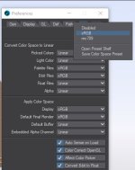
Oh, that menu. Thank you. Tried it now and... it mostly works. Though they match more closely, there is still more fresnel effect visible in the saved image.

Output should match output, at least visibly even if one is still in a larger floating point space.
It would be nice if "Display" were changed to "OpenGL & VPR". It would help users make the mental connection between the two items more immediately by using the same names instead of a close synonym for UX.
Last edited:
prometheus
REBORN
there may be 3-4-5 places to set it all up..
color space edit menu.
vpr image output...wich means you have to use that icon to save vpr out...not f9.
then final render output..this one has to be set to have both render display and render save properly..so it might be you also have a mismatch there.
buffer outputs as well.
there should be no difference at all from vpr vs final rendering...apart from perhaps resolution and refined levels.
prometheus
REBORN
Open GL has nothing to do with VPR rendering really, openGL is one type of display, VPR is antother type of display, both are however display, and it makes a clear distinction between display and render output.Oh, that menu. Thank you. Tried it now and... it mostly works. Though they match more closely, there is still more fresnel effect visible in the saved image.
Output should match output, at least visibly even if one is still in a larger floating point space.
It would be nice if "Display" were changed to "OpenGL & VPR". It would help users make the mental connection between the two items more immediately by using the same names instead of a close synonym for UX.
In preference of the the color space, there is a clear distinction, you have..
Apply color space display (vpr)
Apply color space Final render (f9 still images)
Then you have vpr settings, from which you set VPR image output, that is not to be Display output.
So I think they have all that right really, while I can understand the confusion, I had that as well in the beginning, but you just need to read them carefully and understand the differences.
As for the difference above ..I am unsure how you extracted both images, you either used the vpr icon save out the left display to an image right? and the you must have used screenshot for the right image..that is the closest You may get to check display VS saved image, but..even the screenshot you take may be off and set up differently depending on what software you use to paste it in to an image.

